
- HOME
- PRODUCTS
- SOLUTIONS
-
RESOURCE

 Technology

 User Cases
- NEWS&EVENTS
- CONTACT US
-
ABOUT US
Technology
User Cases
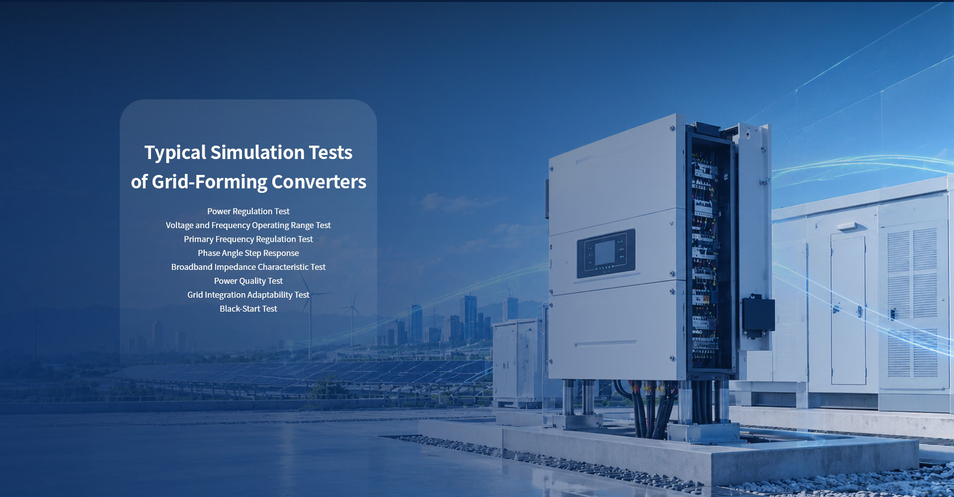
With the advancement of the new power system, a high proportion of new energy sources are replacing conventional synchronous generators. As a result, power grids are characterized by low inertia and weak grid conditions. Traditional grid‑following converters can hardly provide voltage and frequency support, which brings risks of system instability and large‑scale off‑grid tripping. Capable of emulating the characteristics of synchronous machines, grid‑forming converters can offer active voltage and frequency support, islanded operation and black‑start capability. They serve as key equipment to address the stability issues of weak power grids.
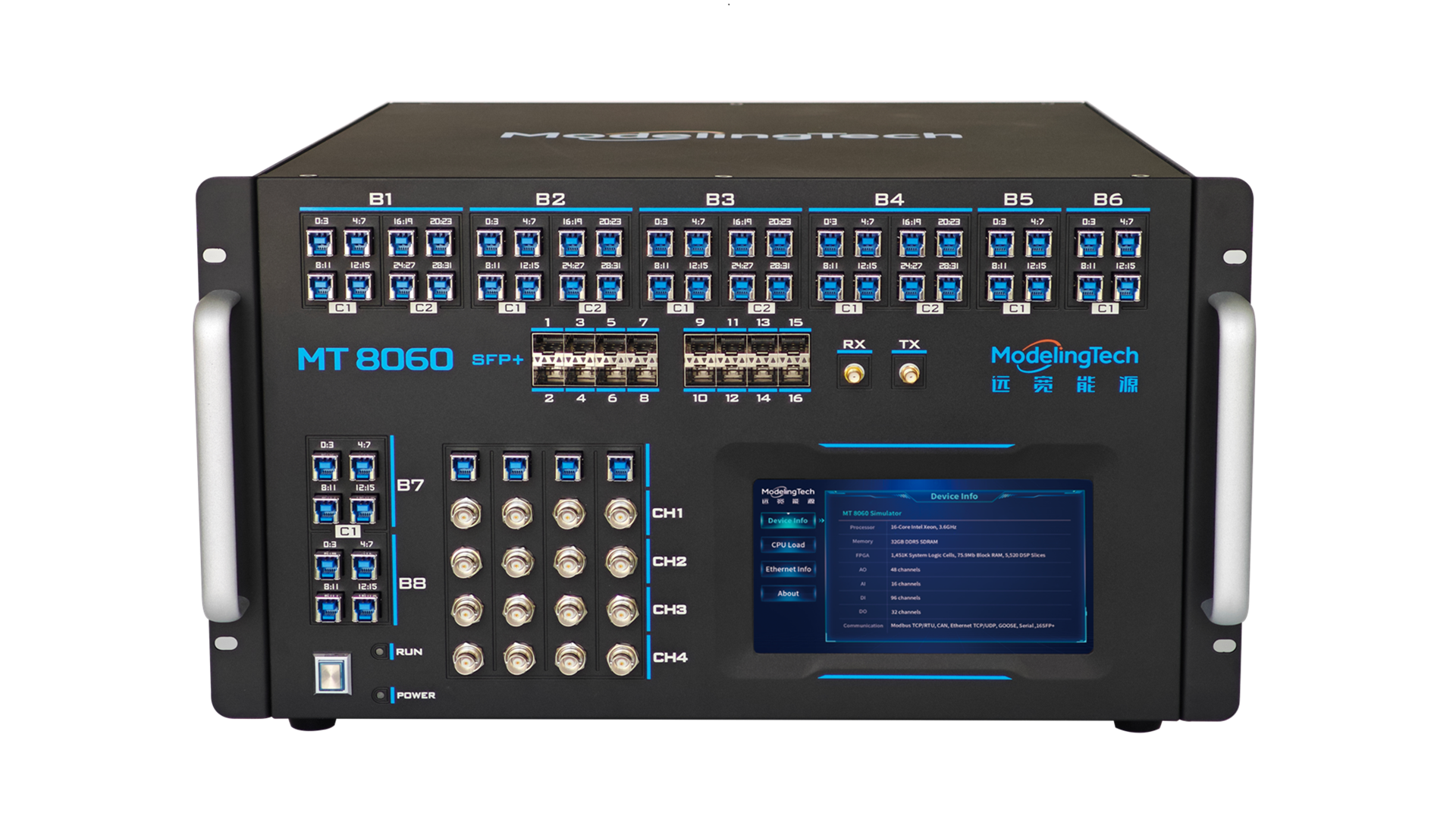
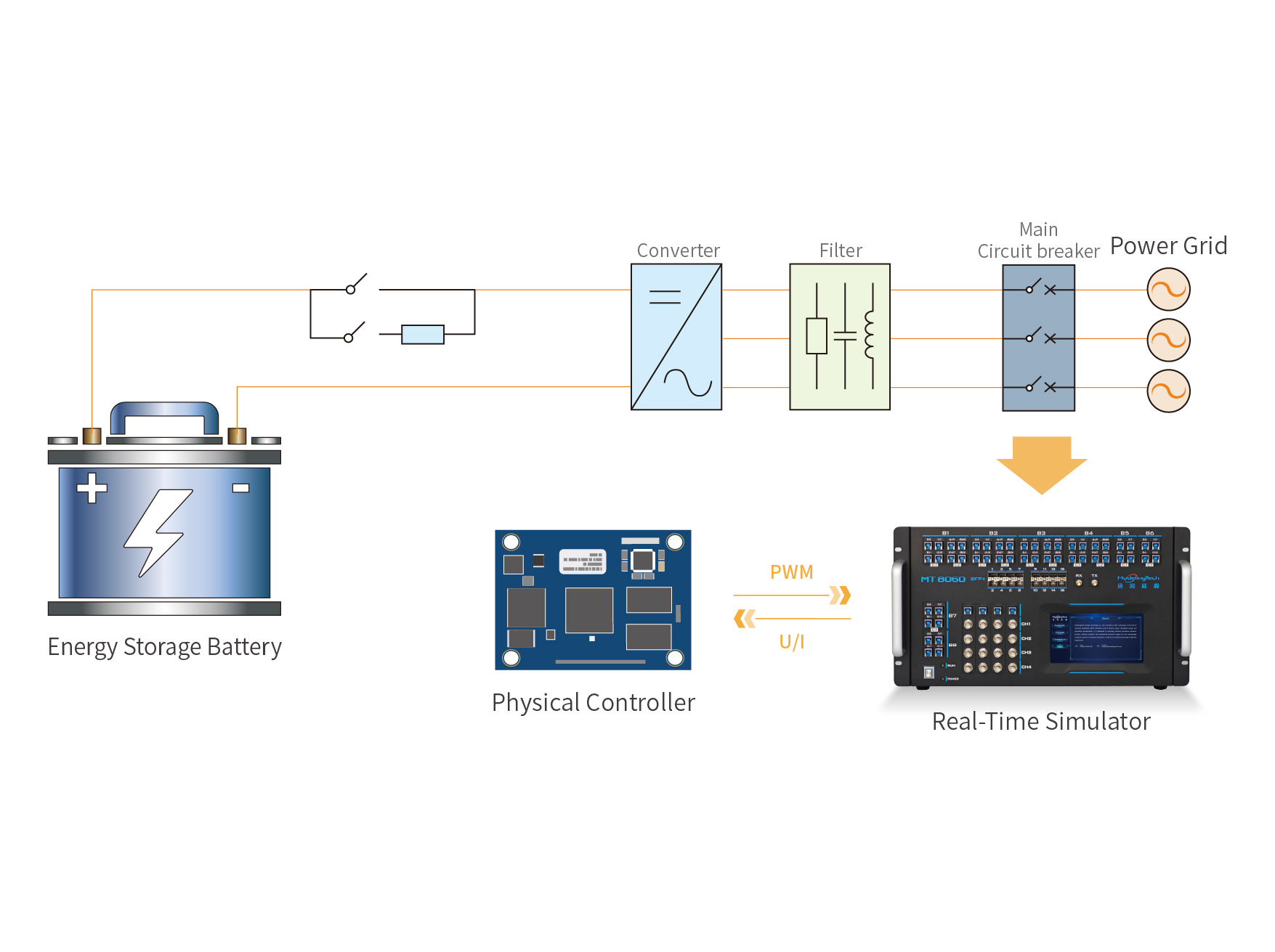
Scheme Description: The ModelingTech MT 8060 real‑time simulation platform is used to simulate a single grid‑forming energy storage converter system. The energy storage battery model (including SOC estimation) is deployed on the CPU with a time step of 50 μs. The power electronic components, including the single grid‑forming energy storage converter and the AC‑side grid, are deployed on the FPGA. Signal‑level hard links with the grid‑forming energy storage converter controller are established through physical I/O interfaces.
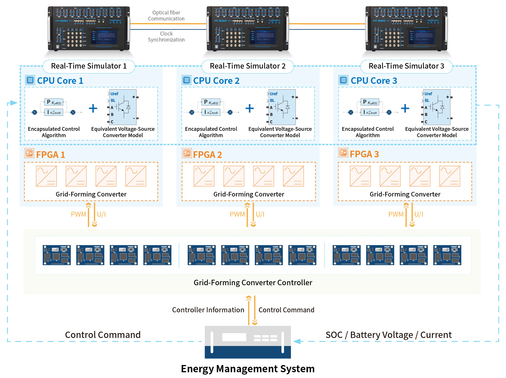
Scheme Description: The ModelingTech MT 8060 simulation platform is used to build a simulation model of an energy storage power station. Taking a grid-connected system with twelve grid-forming energy storage converters as the research object, the system is decoupled into three subsystems at appropriate electrical splitting points and deployed on three real-time simulators. Each simulator performs real-time computation for four grid-forming energy storage converters together with their local power grids.
The control algorithms and equivalent voltage-source converter models are deployed on the CPU with a time step of 50 μs. The power electronic parts, including the parallel grid-forming energy storage converters and the AC-side grid, are deployed on the FPGA. Optical fiber links are adopted among simulators to exchange boundary electrical quantities (voltages and currents), while dedicated clock synchronization cables ensure strictly consistent simulation timing across all nodes. Meanwhile, each simulator connects to a corresponding set of controllers via physical I/O interfaces, forming a complete distributed controller hardware-in-the-loop test cluster.
Scheme Description: The ModelingTech MT 8060 simulation platform is used to emulate a parallel scenario of station‑level multi‑device controllers. The system is decoupled into two subsystems at appropriate electrical splitting points and deployed on the FPGAs of two real‑time simulators. Simulator 1 performs real‑time computation for the cascaded SVG topology together with one grid‑forming converter and its local power grid, while Simulator 2 handles real‑time computation for two grid‑forming converters and their local power grids. Boundary electrical quantities (voltages and currents) are exchanged between simulators via optical fiber links, and dedicated clock synchronization cables guarantee strictly consistent simulation timing for all nodes. Meanwhile, each simulator connects to the corresponding number of controllers through physical I/O interfaces, forming a complete distributed controller hardware‑in‑the‑loop test cluster.
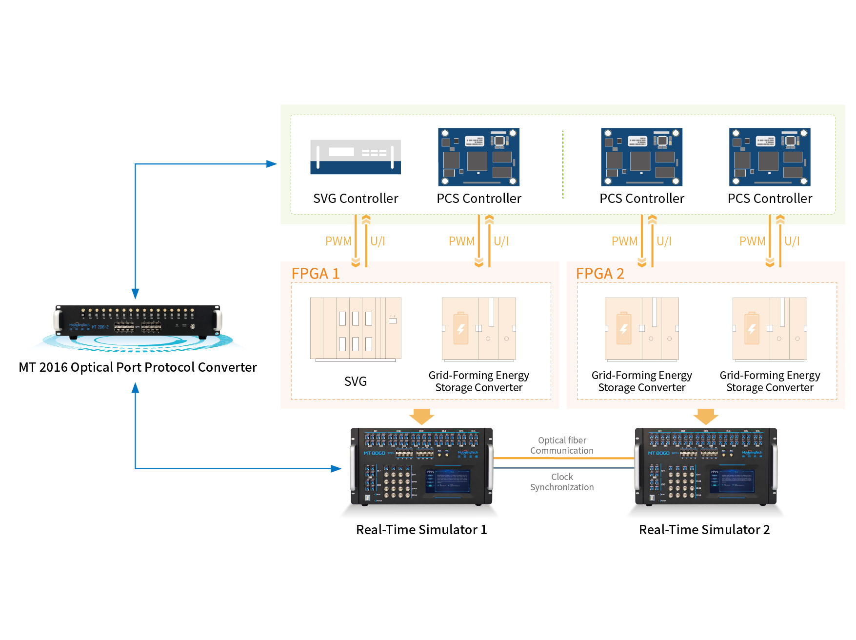


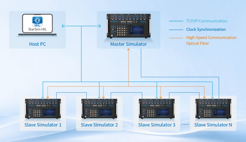
Relying on dedicated clock synchronization cables, the simulators achieve tight time alignment among multiple units. Low‑latency data exchange is realized via high‑speed optical fiber links to enable parallel coordination of multiple simulators. This supports high‑precision real‑time simulation of power electronic devices such as large‑scale wind and solar converters and MMCs, and meets the requirements for clustered simulation expansion.
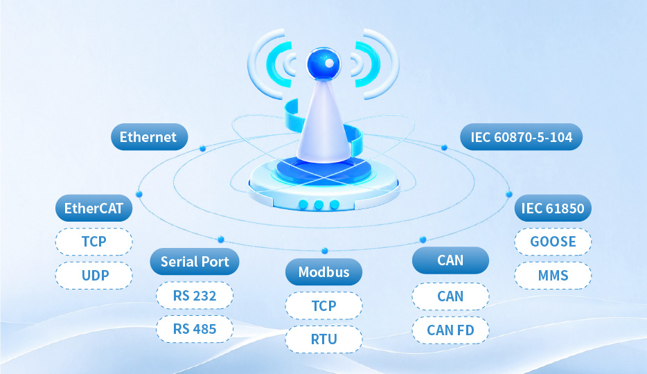
It supports high-speed digital inputs with a wide voltage range (–25 V to 25 V), compatible with industrial inverter interfaces. It also supports professional power communication protocols including Modbus TCP, Modbus RTU, CAN and serial ports, enabling convenient information interaction with controllers.
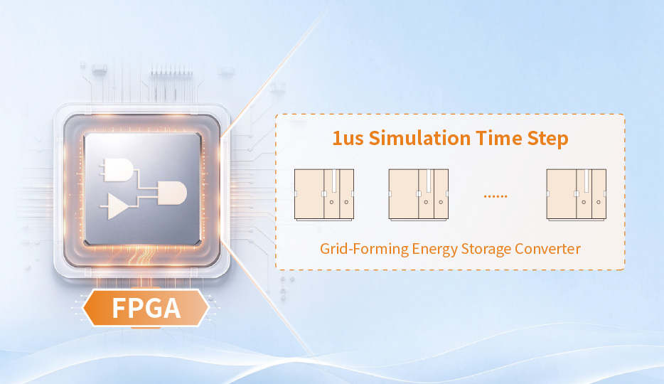
It can simulate 3–5 converter systems at a time step of 1 μs. Equipped with China’s pioneering hybrid modeling method combining LC and RonRoff, it is applicable to a wide range of scenarios from low to high frequencies.
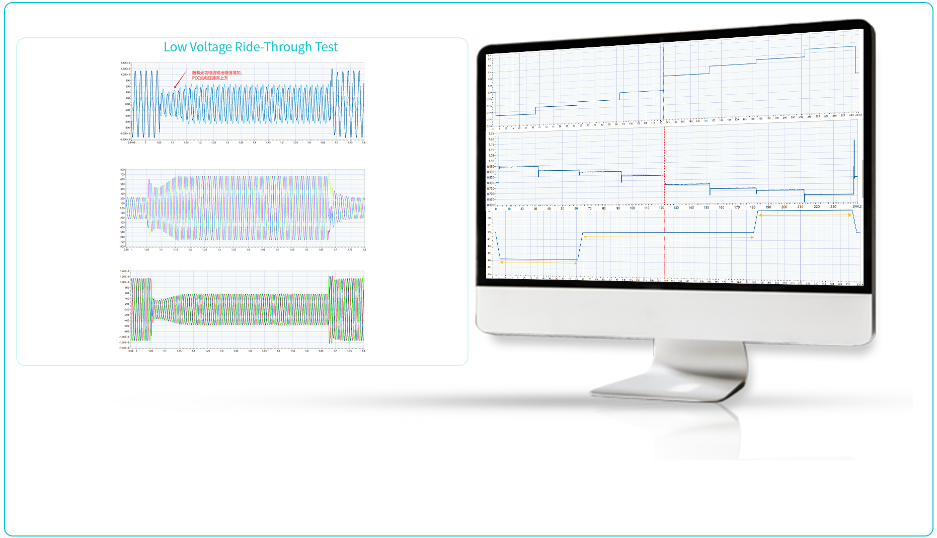
Set the inverter to output rated power, adjust the grid SCR to 10, and conduct the low-voltage ride-through test at 0.2 pu with a fault duration of 625 ms.
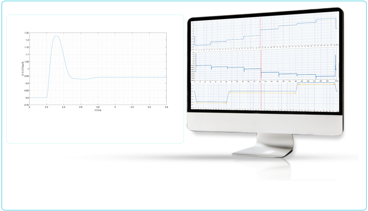
Enable the converter and set its output power to 0.8Pₙ, and activate the primary frequency regulation function of the converter. Adjust the grid frequency to 49.65, 49.75, 49.8, 49.9, 50.1, 50.2, 50.25 and 50.35 Hz respectively. Maintain each frequency point for 30 seconds, and measure the variation of active power output from the converter.
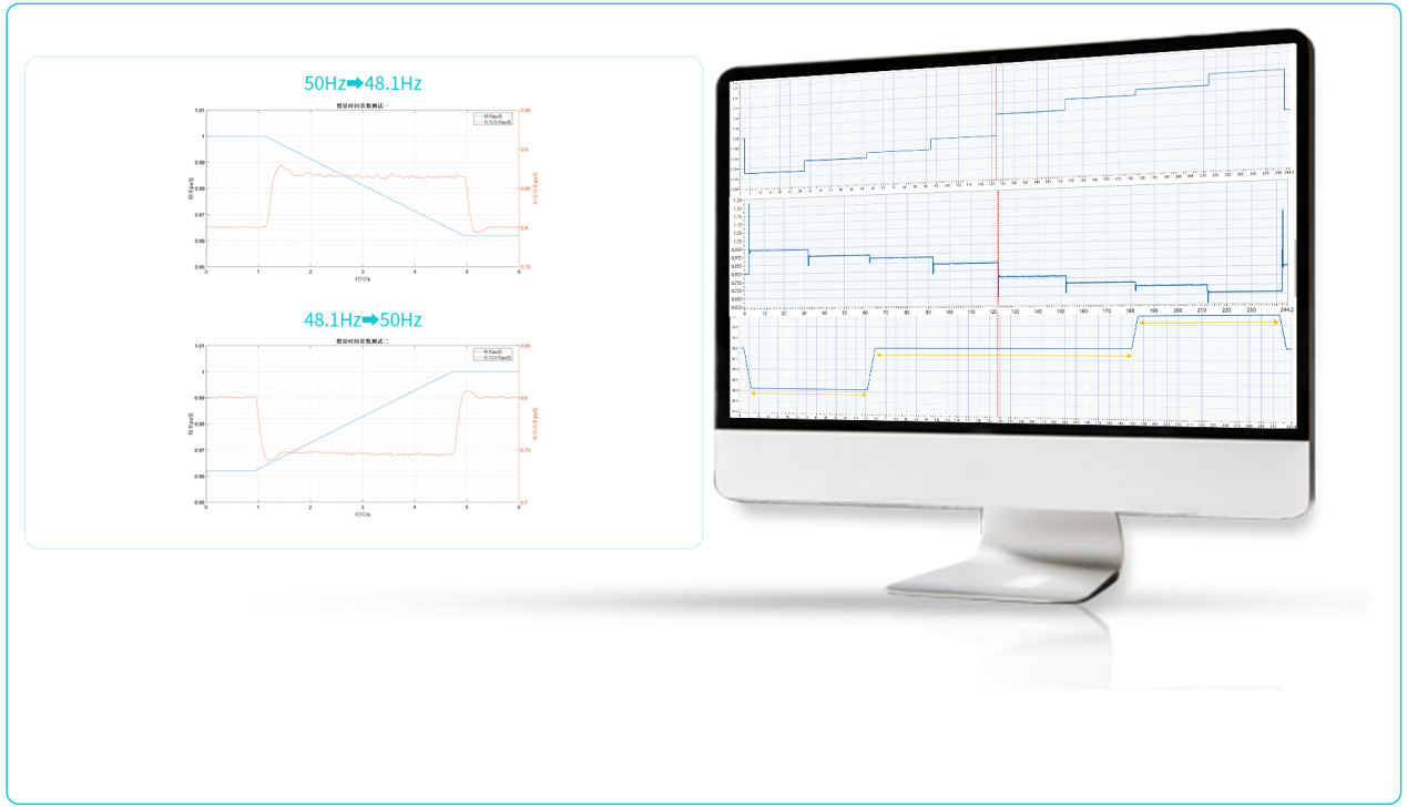
Enable the inverter and set its output power to 0.8Pₙ (176 kW), then disable the primary frequency regulation function of the inverter. HIL CPU programming is adopted to trigger the output of grid frequency.

Leave a message or call to get more details about the product

Learn relevant concepts and technologies

Latest scientific research achievements in top academic journals

Rewarding events and competitions await your participation
Copyright ©上海远宽能源科技有限公司 沪ICP备11009377号-1