
- HOME
- PRODUCTS
- SOLUTIONS
-
RESOURCE

 Technology

 User Cases
- NEWS&EVENTS
- CONTACT US
-
ABOUT US
Technology
User Cases

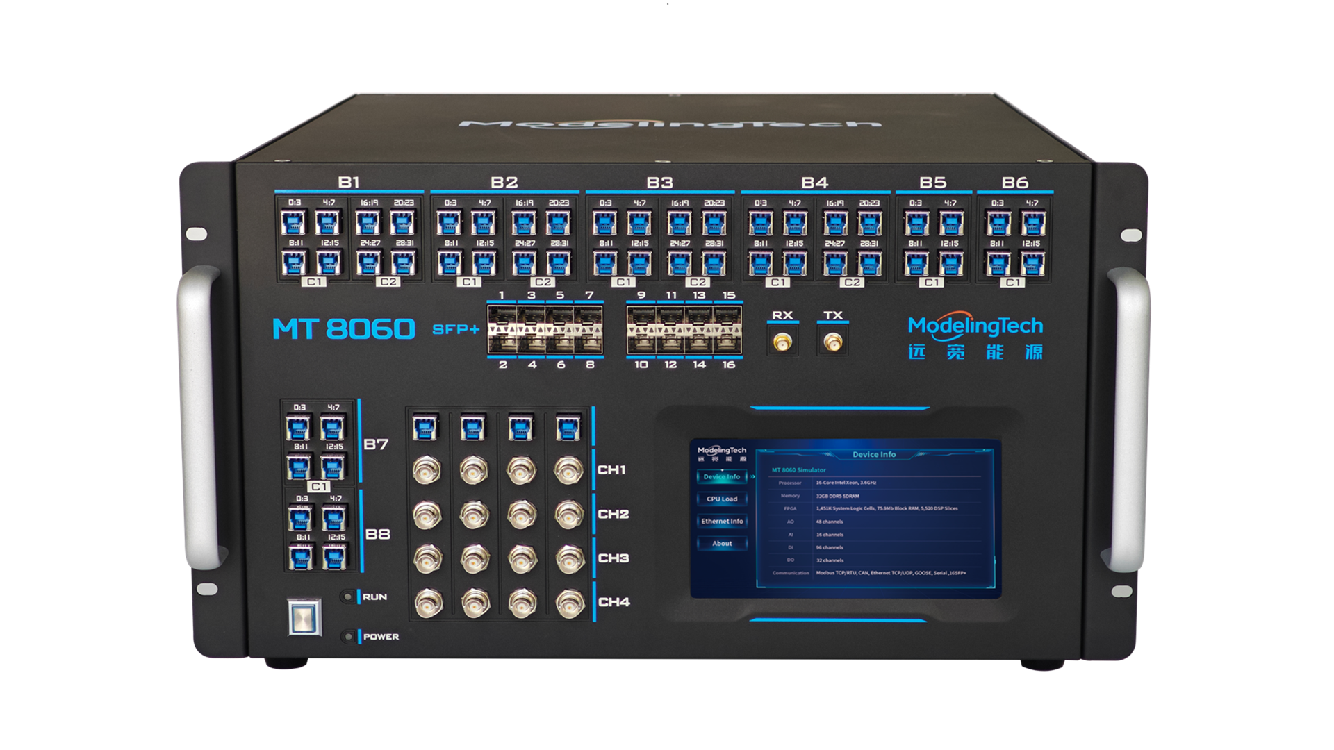
The full-physical-I/O SST controller hardware-in-the-loop testing solution builds a full-physical-I/O hardware-in-the-loop test platform for complete SST controller hardware (master, phase and sub-controllers). It abandons any communication adaptation or conversion and interacts with the controller under test strictly through real physical electrical interfaces, achieving 100% fidelity reproduction at the signal level and providing the ultimate test benchmark for controller performance verification and product finalization.
The platform adopts a distributed multi-simulator collaborative architecture: one master simulator simulates the front-end cascaded H-bridge circuit in real time with a 1 μs time step, while three slave simulators accurately simulate the back-end high-frequency DC-DC converters of each phase with an extremely small 100 ns time step. Real-time data interaction between the four simulators through fiber, together with clock synchronization lines ensuring strict synchronization, forms a high-precision, unified virtual controlled plant.
At the communication and interface level, to achieve the highest signal authenticity, the SST front-end communication interface design principle is: the master simulator sends data to the front-end electro-optical signal conversion boxes through high-speed fiber. The conversion boxes are divided into a DI (digital input) electro-optical conversion box and an AO (analog output) electro-optical conversion box; the former converts the real physical level signals of the sub-controllers into fiber signals output to the power electronics switch model in the master simulator; the latter converts simulated analog quantities such as sub-module capacitor voltages into high-precision physical analog voltage signals output to the sub-controllers. The SST back-end communication interface design principle: the slave simulators interact directly with the corresponding sub-controllers through physical I/O. Thus, at the end of the signal chain, the test platform fully reproduces the electrical connection characteristics and signal timing between real power equipment and controllers, building a high-precision, high-fidelity hardware-in-the-loop test system suitable for final product certification and high-reliability verification.


100% reproduction of real electrical interfaces and signal characteristics, meeting the testing needs of high-fidelity scenarios such as finalization testing, conformity certification and fault reproduction.

To address the limited resources of a single simulator, multiple simulators run in parallel; after decoupling at the system DC side, electrical quantities are transmitted with low latency and strong noise immunity through fiber, and clock synchronization is guaranteed by clock synchronization lines, achieving accurate whole-system simulation of the solid state transformer.

High-speed fiber-optic data interaction and a strict clock synchronization architecture provide the underlying support for energy router simulation with high-voltage multi-stage cascaded H-bridges and large-scale DABs, ensuring system scalability.

The figure shows the measured soft-start process of multiple DABs. According to the primary/secondary separately-enabled startup sequence, the DAB secondary-side voltage rises from 0 V to the rated DC voltage, and the process is consistent with the offline results, verifying the soft-start capability of the system.

Under the 100% active load condition, switch the reactive power command; the reactive power should follow the command change with a response time within 60 ms and steady-state control accuracy within 2%.

Test the 50%-100%-50% output voltage dynamic response; the load-side voltage dynamic response and recovery time should meet the requirements and relevant standards — for example, the recovery time after a DC load voltage change should not exceed 100 ms, and the overshoot should not exceed the voltage setpoint standard.

Leave a message or call to get more details about the product

Learn relevant concepts and technologies

Latest scientific research achievements in top academic journals

Rewarding events and competitions await your participation
Copyright ©上海远宽能源科技有限公司 沪ICP备11009377号-1